English
 Español
  Português
  русский
  Français
  日本語
日本語  Deutsch
  tiếng Việt
  Italiano
  Nederlands
  ภาษาไทย
  Polski
  한국어
한국어  Svenska
  magyar
  Malay
Malay  বাংলা ভাষার
  Dansk
Dansk  Suomi
Suomi  हिन्दी
  Pilipino
  Türkçe
  Gaeilge
  العربية
  Indonesia
  Norsk
Norsk  تمل
تمل  český
český  ελληνικά
  український
  Javanese
  فارسی
فارسی  தமிழ்
தமிழ்  తెలుగు
  नेपाली
  Burmese
  български
  ລາວ
ລາວ  Latine
  Қазақша
  Euskal
  Azərbaycan
  Slovenský jazyk
  Македонски
  Lietuvos
  Eesti Keel
  Română
  Slovenski
  मराठी
मराठी  Srpski језик


Heim
>
Produkte > Metal Chip Briquetting Machine
>
Eisenspäne / Aluminiumspäne / Gusseisenspäne parallel


Eisenspäne / Aluminiumspäne / Gusseisenspäne parallel
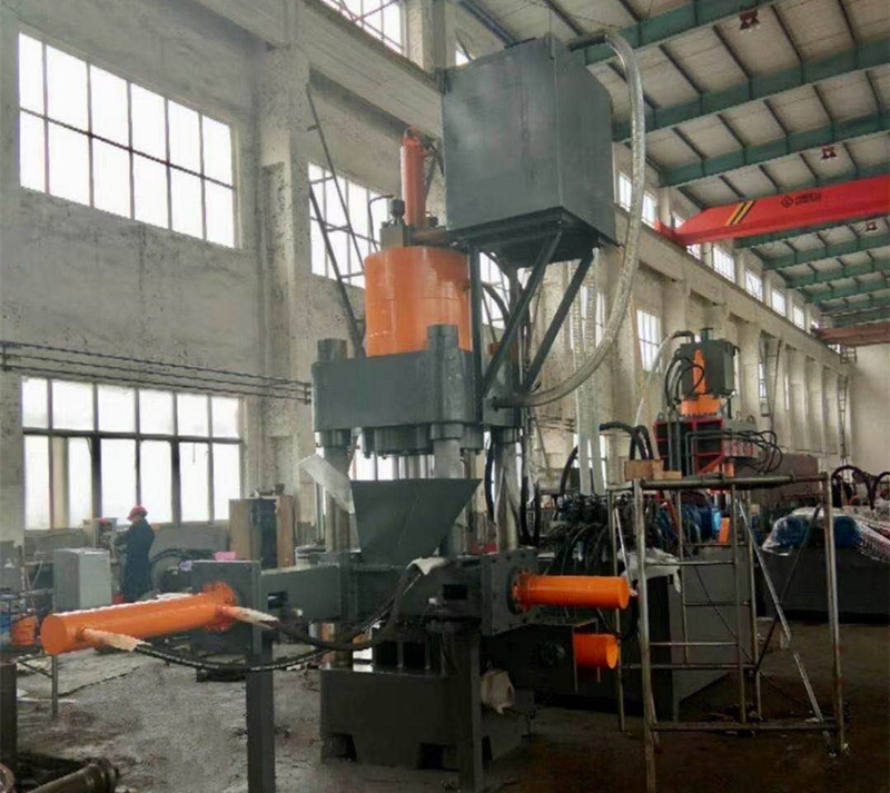
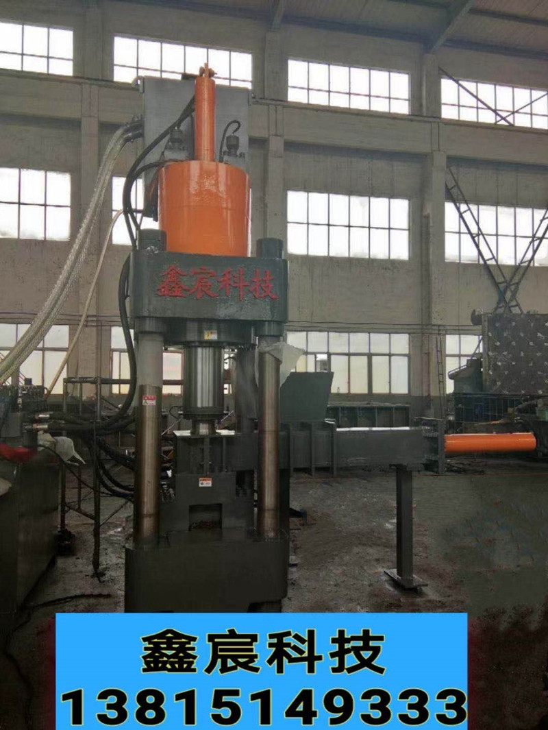
The crumb cake machine is suitable for aluminum alloy profile plants, steel casting plants, aluminum casting plants, copper casting plants, etc. It can remove aluminum scrap, aluminum dust, steel scrap, steel slag, steel pin, iron scrap, copper scrap, copper rice, zinc scrap , Lead scrap and other briquette
Modell:Y83
Anfrage absenden
Produktbeschreibung
630 tons of shavings and machine
Chip and machine, chip and machine manufacturer, hydraulic chip and machine, cast iron chip cake machine, steel powder chip machine, titanium chip machine, aluminum chip machine, automatic metal chip machine, high-capacity aluminum chip machine Parallel machine. Copper pin chip parallel machine, steel chip cake machine, waste lead chip cake machine
1. Usage and characteristics
(1. Zweck
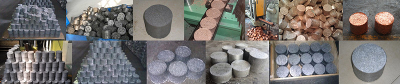
1. It is mainly used to press various metal scraps (cast iron scraps, copper scraps, aluminum scraps, etc.) into blocks through special molds, which facilitates the transportation and processing of metal scraps. It is used in steel plants, non-ferrous metal plants, and smelting. Ideal equipment for factories.
2. Diese Maschine ist mit geeigneten Messern, Formen und anderen Hilfswerkzeugen ausgestattet und kann auch zum Korrigieren, Pressen, Formen, Strecken und zur allgemeinen Druckverarbeitung verwendet werden, wenn die Anforderungen an Schneiden und Präzision nicht hoch sind.
(2) Merkmale
1. This machine adopts hydraulic transmission, working smoothly and low noise.
2. Diese Maschine verwendet Jog, Einzel- und kontinuierliche Arbeitsumwandlung mit guter Automatisierung, bequemem Betrieb und hoher Produktionseffizienz.
2. Gesamtstruktur und Arbeitsprinzip
1. Gesamtstruktur Die Maschine besteht hauptsächlich aus einem mechanischen System (Hauptteil), einem elektrischen System, einem Hydrauliksystem usw.
(1) Der Hauptmotor besteht hauptsächlich aus einem Hauptpressmechanismus und einem Druckmechanismus.
1. Der Hauptpressmechanismus besteht aus Oberbalken, Unterbalken, aufrecht stehender Säule und Materialpresszylinder. Der obere Balken, der untere Balken und der mittlere Balken sind alle geschweißte Bauteile. Der obere und untere Träger bestehen aus aufrechten Säulen, aufrechten Kappen und aufrechten Muttern, um den Hauptrahmen des Hauptrahmens zu bilden. Der Druckölzylinder ist eine Frontflanschstruktur und am Oberbalken befestigt. Die Kolbenstange des Materialölzylinders ist durch Innengewinde mit der oberen Matrize verbunden, und die obere Matrize wird vom Ölzylinder angetrieben, um sich linear auf und ab zu bewegen. Der Druckölzylinder ist ein kombinierter Ölzylinder, der aus einem einfachwirkenden kolbenartigen Hauptdruckölzylinder und einem schnell einarbeitbaren Ölzylinder besteht. Der schnell einarbeitbare Ölzylinder ist ein doppeltwirkender kolbenartiger Ölzylinder mit Kolben, Führungshülsen usw. und einem Dichtring. Das Abblendlicht dient gleichzeitig als Arbeitsbühne und ist mit Hilfsformen und Druckzylindern ausgestattet.
2. The pushing mechanism is composed of a pushing cylinder and auxiliary molds. The pushing cylinder is a piston type double-acting cylinder, which is fixed on the lower beam of the main machine with a front flange structure, and the front end is connected with the ejection pad of the auxiliary mold. The auxiliary mold is composed of an upper mold, a lower fixed mold base, a mold release pad, an inner mold sleeve, a lower mold pressing plate, and a feeding hopper. The upper mold is connected to the material pressing oil cylinder with external threads and the piston rod uses the material pressing oil cylinder to move up and down to compact the material in the inner mold sleeve. The lower fixed mold base is fixed on the lower beam with screws, and a surface-treated wear-resistant inner mold sleeve and die pad are installed in the middle, and the inner mold sleeve is fixed in the lower fixed mold base with a molding plate (see the attached mold structure diagram).
3. The hydraulic oil cylinder is composed of a material pressing oil cylinder and a material pushing oil cylinder. The pressure oil cylinder is composed of a main pressure oil cylinder and a quick work feed oil cylinder. The main pressure oil cylinder is a piston single-acting oil cylinder and also adopts a piston structure. Except for the front cavity without oil, the structure is the same as the fast work feed oil cylinder and the push oil cylinder Consistent. The quick-working oil inlet cylinder and the pushing oil cylinder are both piston-type double-acting oil cylinders. The piston is equipped with a sealing ring to form two oil chambers in the cylinder. When the high pressure oil acts on the rear cavity (also known as the large cavity) or the front cavity (Also known as small cavity) when pushing the piston to make a straight reciprocating motion in the cylinder, to achieve the purpose of driving the moving parts. At the same time, the cylinder port is provided with a guide sleeve for supporting, guiding and sealing the piston rod.
(2) The electrical system is composed of two parts: a motor control circuit and an action control circuit.
(3) Das Hydrauliksystem besteht aus einem Öltank, einer Pumpstation, einer Ventilstation usw. Der Hauptmotor ist in zwei Teile unterteilt: den Speiseölkreislauf und den Hauptdruckölkreislauf.
2. Arbeitsprinzip
Fügen Sie das zu verarbeitende Material aus dem Trichter in die untere Forminnenhülse ein, drücken Sie den automatischen Knopf. Die obere Form komprimiert das Material auf den vom System eingestellten Druck und kehrt zum Entladen für 1 bis 2 Sekunden (von SPS eingestellt) zurück. und der Schubzylinder kehrt zurück Wenn er an Ort und Stelle ist, bewegt sich die obere Form nach unten, um die Metallspäne in der inneren Formhülse aus dem Formhohlraum herauszudrücken, und kehrt zurück, und der Druckzylinder bewegt sich vorwärts, um den Presskörper aus dem Formhohlraum herauszudrücken, und ist fertig ein Arbeitszyklus.
Viertens elektrisches System
(1) Overview It is powered by a 380 volt AC power supply and consists of two parts: the main circuit and the control circuit.
1. The main circuit is composed of two parts: the motor circuit and the emergency stop circuit, which is powered by a 380V power supply. The motor circuit directly supplies power to a y-type three-phase asynchronous motor from the circuit power supply to drive a plunger pump and a gear pump. The emergency stop circuit consists of an emergency stop button and intermediate relay. In the event of an accident, just press the emergency stop button to stop the motor and interrupt all actions.
2. The control circuit is composed of two parts: a motor control loop and an action control loop (also called plc input and output loop). The motor control circuit is composed of motor start, stop and motor work display, etc. The action control circuit is composed of the forward and backward movements of the main pressure cylinder and the forward and backward movements of the pushing cylinder, which are mainly used to control the mechanical work.
(1) Polymer circuit breaker qf model dz47-80 (80a) power control, used to cut off and switch on system power.
(2) Motor m Modell y220l2-4, Leistung 22 kW, Geschwindigkeit 980 U / min, doppelte Abtriebswelle wird verwendet, um gleichzeitig eine Axialkolbenpumpe und eine Zahnradpumpe anzutreiben.
(3) Taste sb1 Modell la18-22 / 220V Motor zum Anhalten
(4) Taste sb2 Modell la18-22 / 220V Motorstart
(5) Control transformer tc model bk-250/380/220v control loop power control
(6) Intermediate relay ka model cjx1-12/220v emergency stop control
(7) Hubschalter sq Modell jlxk1-411 Hubsteuerung
(8) Indicator light hl model slc22 power indicator, motor working indicator, fault display
(9) AC-Schütz km Modell cjx1-63 / 380v Motorsteuerung
(11) Transfer switch sa model psc22-d jog, single, continuous conversion
(12) Ventilmagnet yv Modell mfb1-5.5yc Umkehrsteuerung
(13) Aktionssteuerung des speicherprogrammierbaren SPS-Modells cpm1a-30cdr
(14) Not-Aus-Taster sb Modell pbc22-c Not-Aus
(2) Description of electrical principle
1. Switching on and off the power supply is realized by the high breaking circuit breaker qf.
2. Motor start and stop (star-delta start control)
Turn on the power, the power indicator hl is on; press the motor start button sb1, the button is normally open touch
Wenn der Punkt geschlossen ist, werden die Spulen der Wechselstromschütze km1 und km3 erregt, und die normalerweise offenen Kontakte werden geschlossen, um die Spulen kontinuierlich mit Strom zu versorgen. Die Hauptkontakte des Wechselstromschützes km1 sind geschlossen und der Motor wird erregt. Nach einer Verzögerung von 3 s wird das Wechselstromschütz km2 eingeschaltet und km3 abgeschaltet. Der Motor geht in den normalen Betriebszustand über; die Signalleuchte hl2 leuchtet, um anzuzeigen, dass die Ölpumpe normal arbeitet; Drücken Sie die Motorstopptaste sb2, der normalerweise geschlossene Kontakt wird getrennt, die Wechselstromschützspule wird abgeschaltet und der normalerweise offene Kontakt wird getrennt, der Hauptkontakt wird getrennt und die Stromversorgung wird unterbrochen. Der Motor m stoppt, wenn der Strom wird abgeschaltet,
Hot-Tags: Span und Maschine, Metallspan und Maschine, Gusseisen-Spanmaschine, Stahlspanmaschine, Titan-Spanmaschine,
Anfrage absenden
Bitte zögern Sie nicht, Ihre Anfrage im untenstehenden Formular zu stellen. Wir werden Ihnen innerhalb von 24 Stunden antworten.